timestamp : Wed Sep 17 14:45:31 PHT 2008
general problem specification : microntroller controlled pick and place operation.
project specifications :
Using a Z8 microcontroller (or another readily available microcontroller)
and a RVM1 interface unit, perform pick and place of single object.
The object will be moved from coordinates (380, 0, 0) mm to
coordinates (0, 380, 115) mm.
The manipulator motion will be controlled using the Z8 microntroller.
The Z8 microntroller board will be able to drive the RVM1 manipulator
motors
and sample the encoder and limit switch outputs using the RVM1 interface
box.
The Z8 microcontroller may be programmed using C.
Control of the manipulator will be performed by driving the RVM1 joint
motors
using a PWM signal from the Z8 microcontroller. Position feedback
is achieved
by monitoring the signals from the encoders and the limit switches.
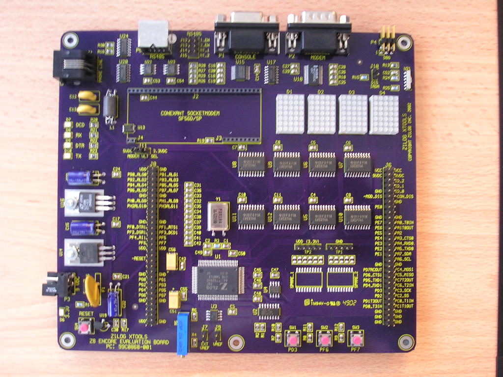
information on the Z8 microcontroller board :
Information on the Z8 Encore microcontroller evaluation
board as well as
relevant software are available in the lab. Please read the documents
throughly. A simulator is included in the Zilog Development Studio
(ZDS) package.
Knowledge of C programming is required. I/O pins of the Z8 Encore
are available
through standard header pins.
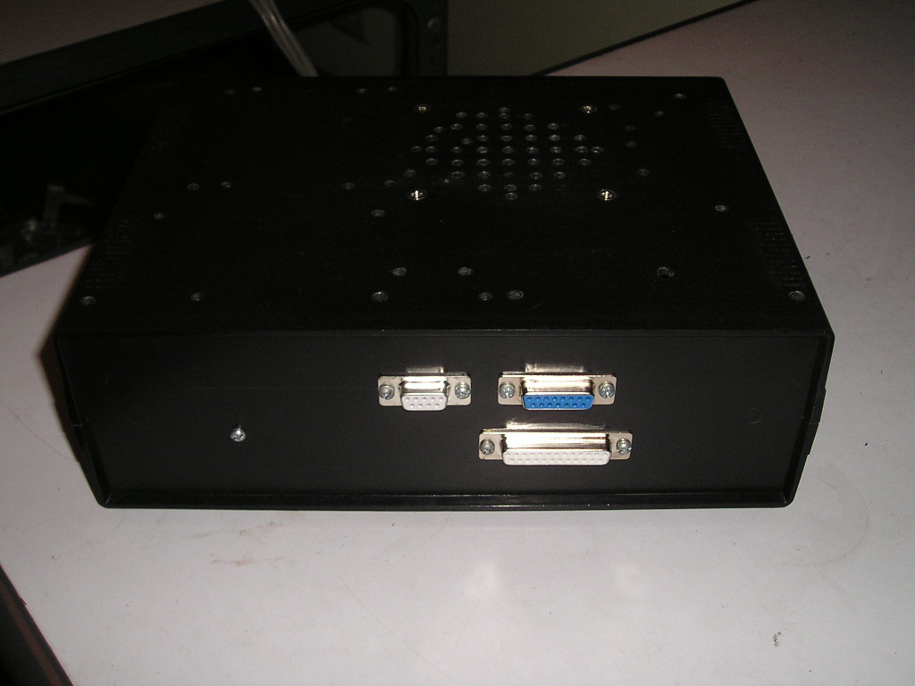
information on the RVM1 interface box :
The "box" interfaces a controller (such
as the Z8 Encore) with the RVM1
manipulator. The "box" provides motor drivers for the RVM1 motors
and
signal conditioning for the signals from the encoders and limit switches.
The "box" has three main ports, namely the PWM motor drive input port,
encoder output port, and current sense port.
The PWM motor drive input port is a DB-15 female connector
with the following pin assignments.
1 - joint 1 input A (cw, toward joint 1 limit switch)
2 - joint 1 input B (ccw, away from joint 1 limit switch)
3 - joint 2 input A (link 2 up)
4 - joint 2 input B (link 2 down)
5 - joint 3 input A (link 3 up)
6 - joint 3 input B (link 3 down)
7 - joint 4 input A (link 4 up)
8 - joint 4 input B (link 4 down)
9 - joint 5 input A (ccw, away from joint 5 limit switch)
10 - joint 5 input B (cw, toward joint 5 limit switch)
11 - gripper input A (close)
12 - gripper input B (open)
13 - joint 2 unlock
14 - joint 3 unlock
15 - GND
Each joint has 2 corresponding inputs (A and B) for speed and
direction control.
These inputs should be driven by PWM signals at TTL levels.
The unlock inputs
are also TTL level and active high.
The encoder output port is a DB-25 female connector
with the following pin assignments.
joint 1 encoder A, B, Z signals and limit switch - pins 1, 2, 3, 4,
respectively.
joint 2 encoder A, B, Z signals and limit switch - pins 5, 6,
7,8, respectively.
joint 3 encoder A, B, Z signals and limit switch - pins 9, 10,
11, 12, respectively.
joint 4 encoder A, B, Z signals and limit switch - pins 13, 14,
15, 16, respectively.
joint 5 encoder A, B, Z signals and limit switch - pins 17, 18,
19, 20, respectively.
GND - pin 25
These signals are TTL level. Limit switch signals are active high.
Pins 21, 22, 23, 24 are always asserted when the "box" is on.
The current sense port is a DB-9 female connector
with the following pin assignments.
1 - joint 1 current sense
2 - joint 2 current sense
3 - GND
4 - joint 3 current sense
5 - joint 4 current sense
6 - GND
7 - joint 5 current sense
8 - gripper current sense
9 - GND
10 - GND
The Z8 microcontroller evaluation board and the RVM1 interface box will
be provided
by the lab. Connections between the Z8 board and the interface
box can be achieved
using a ribbon cable, ribbon cable connector, and DB-25 and DB-15 male
connectors.
project output :
You will first need to construct a connector-cable between the Z8 microntoller
board
and the RVM1 interface box. You will most likely need two ribbon
cable connectors,
ribbon cable, DB-25 and DB-15 male connectors. It is up to
you to determine
which Z8 Encore I/O port(s)/pin(s) you will use for the project.
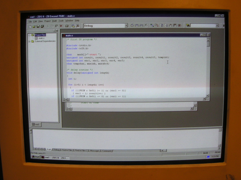
C program (and relevant files) that will be compiled and then loaded
to the
Z8 microntroller through the ZDS software
installed in a PC.
tips and hints :
To control the speed of the motors, use PWM signals of appropriate duty
cycle.
Selecting input A or input B determines the motor direction.
Start out with low duty cycles until you are confident with what you
are doing.
Use a maximum of 20% duty for joint 1, 50% for joint 2, 30% for
joint 3, and 25% for
joint 4 and 5, and 10% for the gripper.
You need to unlock joint 2 or joint 3 before moving them.
The encoders are optical incremental quadrature encoders. You
need to reference the
readings to an absolute position. These are what the limit switches
are for.
Refer to the following for the motor reduction ratios and encoder resolutions.
| item | J1 | J2 | J3 | J4 | J5 | unit |
| reduction ratio | 100 | 165.3 | 110 | 180 | 110 | --- |
| encoder resolution | 200 | 200 | 200 | 96 | 96 | pulses/rotation |
additional requirements / information :
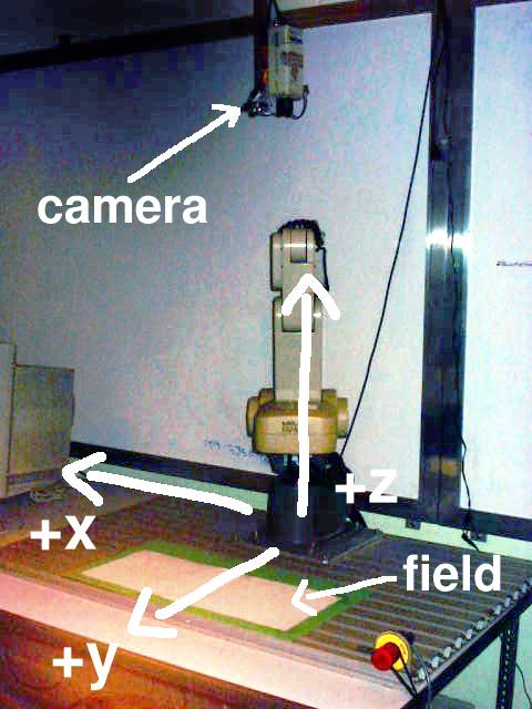
Assume that the coordinates will be given. you may compile this
with your code.
All coordinates are reference as shown in manipulator.jpg.
The object is a cylinder with diameter = 31 mm and height = 37 mm.
The C program and project files should be compatible with the
supplied ZDS software.
There is definitely more information that you need to know that may
not be here.
Ask if unsure.
as usual :
10 minute report Q&A
complete docs
3 weeks for submission and demonstration.
verify your solution, consult me
hands on the second week